
Products · IBC Fill Head
Controlled & Contained Filling From Process Line to IBC
Connect Your Process Line to the IBC With Better Dust Control
The ISL IBC Fill Head is designed for the point where powders, granules or pellets are transferred from a process line into an IBC.
Its cyclonic design, integrated vent pipe and IBC sealing arrangement help create a controlled filling interface. When paired with an appropriate dust collector system, the Fill Head is designed to provide maximum dust containment during material transfer.
Available in Electrical Lifting Column, Pneumatic Cylinder and Manual configurations, the Fill Head can be selected according to your process, level of automation and operating requirements.

Electrical Lifting Column
1 × lifting column · 200 mm stroke
Pneumatic Cylinder
2 × pneumatic cylinders · 200 mm stroke
Manual
Manual operation
What Does an IBC Fill Head Do?
Create a Controlled Interface Between Your Process & IBC
Filling an IBC is more than simply directing material into a container.
As powder enters the IBC, displaced air needs a controlled path to leave the vessel, while the filling connection needs to remain properly positioned over the IBC inlet.
The ISL Fill Head addresses these requirements through a dedicated filling interface.


Connect
Installed at the point where material moves from the process line into the IBC.

Cover
When lowered, the Fill Head covers the IBC inlet during filling.

Vent
An integrated vent pipe allows displaced air to exhaust from the IBC as material is loaded.

Contain
The cyclonic design can be paired with an appropriate dust collector system to support dust containment.
Choose Your Fill Head
Three Actuation Options. One Controlled Filling Function.
Different production environments require different levels of automation. ISL provides three Fill Head configurations:
 Electrical Lifting Column
 Type
For automated vertical positioning
The Fill Head is operated using a lifting column. When lowered, it covers the IBC inlet and provides the filling connection.

 Download Electrical Fill Head Datasheet
Key Specifications
 1 × lifting column
- 200 mm stroke length
- 220 V, 1 Phase, 50 Hz
- Inductive lid sensor
- IP66 junction box
- Custom mounting connection available
- Approx. 55 kg net weight
Different stroke lengths are available on request.
The Technology Behind Controlled IBC Filling
Cyclonic Fill Head Design
The Fill Head incorporates a cyclonic design at the filling interface.
When combined with an appropriate dust collector system, this design is intended to provide maximum dust containment during the transfer of material from the process line into the IBC.
An integrated vent pipe provides a dedicated route for displaced air to exhaust from the IBC as powder is loaded.
This creates a more controlled filling environment around the IBC inlet.
How the IBC Fill Head Works
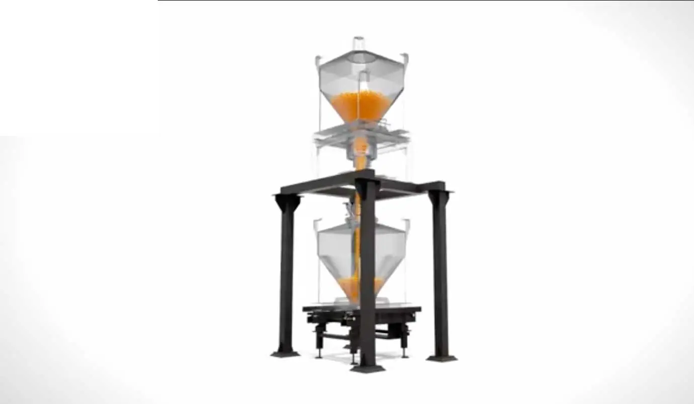
From Process Line to Filled IBC

Material Arrives
Product travels through the process line toward the IBC filling point.
IBC Is Positioned
The IBC is positioned beneath the Fill Head.

Fill Head Lowers
The selected actuation system lowers the Fill Head so that it covers the IBC inlet.

Material Is Transferred
Powder, granules or pellets move from the process line into the IBC.

Displaced Air Is Vented
As material enters the IBC, displaced air is exhausted through the integrated vent pipe.

Dust Is Managed
When paired with an appropriate dust collector system, the cyclonic Fill Head design supports dust containment during filling.

Filling Is Completed
The Fill Head can then be raised and the filled IBC moved to the next stage of the process.
The exact filling sequence and control logic depend on the selected Fill Head configuration and the wider system.
Designed for Different Bulk Materials
One Fill Head Platform for Multiple Materials
The datasheets specify the Fill Head for handling:

The appropriate construction and system configuration should be selected according to the material and process requirements.
Built Around the IBC
A Filling Component Within a Larger Material Handling System
The Fill Head is designed to work as part of an IBC filling arrangement rather than as an isolated component. A typical process connection can follow:

This makes the Fill Head the controlled interface between the incoming material stream and the IBC.
The final arrangement can be engineered around the IBC configuration, process line and downstream handling requirements.
Construction & Materials
Specified for Process Applications
The three Fill Head configurations use stainless steel for their specified contact parts.
Note: The FDA-compliant specification in the datasheets refers to the listed elastomers, not the complete Fill Head.
Technical Specifications
Fill Head Configurations at a Glance
Electrical Lifting Column Fill Head
Automated Vertical Positioning
The Electrical Lifting Column version uses one lifting column to move the Fill Head into position.
- Actuation
- 1 × Lifting Column
- Stroke
- 200 mm
- Electrical Supply
- 220 V, 1 Phase, 50 Hz
- Lid Sensor
- Inductive, M30, 10–36 VDC PNP, N.O., IP65
- Junction Box
- Polycarbonate, IP66
- Mounting
- Stud bolts
- Dimensions
- 580 × 580 × 700 mm
- Approx. Net Weight
- 55 kg
Different stroke lengths can be provided on request.
Pneumatic Cylinder Fill Head
Pneumatic Actuation for Controlled Positioning
The Pneumatic Cylinder version uses two pneumatic cylinders and an air control assembly to operate the Fill Head.
- Actuation
- 2 × Pneumatic Cylinders
- Stroke
- 200 mm
- Air Pressure
- 4–6 bar
- Air Volume
- 4.37 L/cycle
- Tubing
- 12 mm
- Reed Switches
- 12–48 VDC, 1A, N.O., IP65
- Lid Sensor
- Inductive, M30, 10–36 VDC PNP, N.O., IP65
- Air Control
- Double solenoid valve, 24 VDC, IP65
- Junction Box
- Polycarbonate, IP66
- Mounting
- Stud bolts
- Dimensions
- 625 × 667 × 745 mm
- Approx. Net Weight
- 70 kg
Different stroke lengths can be provided on request.
Manual Fill Head
Simple Manual Positioning
The Manual Fill Head is designed for applications where powered actuation is not required.
- Actuation
- Manual
- Mounting
- Stud bolts
- Dimensions
- 580 × 580 × 435 mm
- Approx. Net Weight
- 26 kg
The mounting connection can be customized according to client requirements.
Mounting & Integration
Designed to Fit Your Process Layout
The Fill Head is mounted using stud bolts as the standard mounting connection.
The datasheets specify that the mounting connection can be customized to suit the client's requirements.
This allows the Fill Head mounting arrangement to be considered around the existing process line, IBC configuration and facility layout.
Lid Detection & Positioning
Designed With Process Feedback
The actuated Fill Head configurations include an inductive lid sensor.
This allows the actuated Fill Head configuration to incorporate position-related sensing into the wider control system.
Which Fill Head Is Right for You?
Choose the Actuation Based on Your Process
Fill Head + Dust Collection
A More Controlled Filling Environment
The Fill Head is designed to work alongside an appropriate dust collector system.
Its cyclonic design supports dust containment, while the integrated vent pipe provides a route for displaced air to leave the IBC during filling.
For the complete installation, the dust collection arrangement should be selected according to the material, process conditions and required system performance.
Complete IBC Filling System
The Fill Head Is One Part of the Process
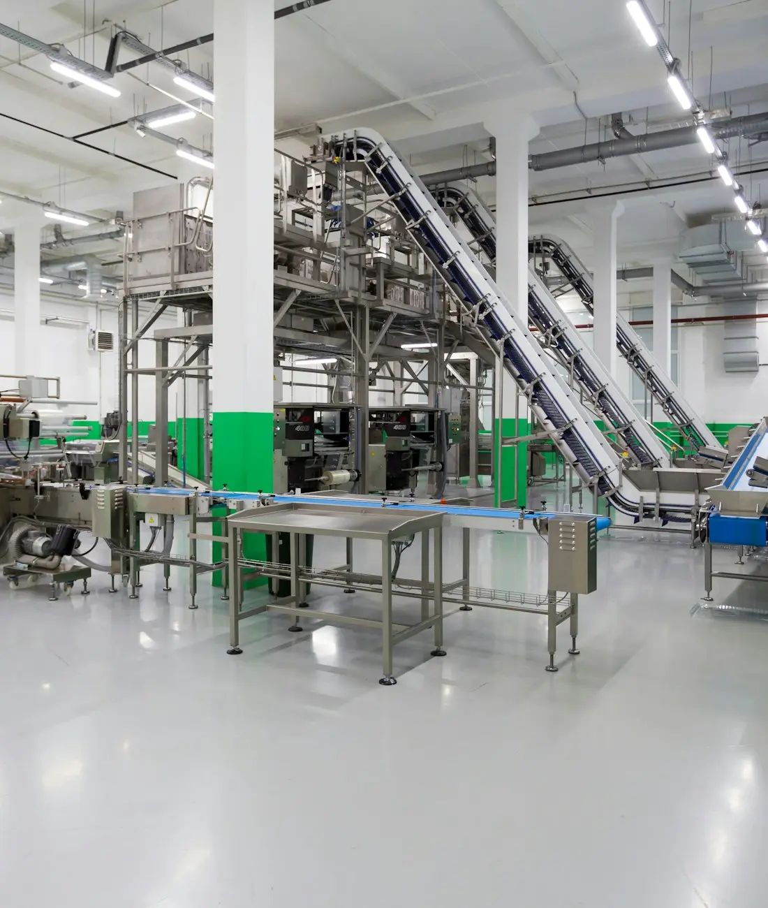
An IBC filling system can incorporate several elements around the Fill Head.
Process Line
Provides the incoming material stream.

Fill Head
Creates the controlled connection to the IBC.

Dust Collection
Manages displaced air and dust as part of the overall filling arrangement.

IBC
Receives and stores the bulk material.

Identification
IBC identification options can be used to associate the vessel with the relevant batch.

Downstream Handling
The filled IBC can then move to storage, blending, discharge, dosing or another process stage.
Engineered Around Your IBC
Standard Technology. Configurable Installation.
ISL's Fill Head configurations provide a defined filling interface while allowing certain installation parameters to be adapted.
The datasheets specifically provide for:
This provides flexibility when incorporating the Fill Head into an existing or new IBC handling system.
Frequently Asked Questions
An IBC Fill Head is installed at the point where material is transferred from a process line into an IBC. It covers the IBC inlet during filling and provides an integrated vent path for displaced air.
The datasheets specify the Fill Head for powders, granules and pellets.
The Fill Head has a cyclonic design and, when paired with an appropriate dust collector system, is designed to provide maximum dust containment.
As powder is loaded into the IBC, air inside the vessel is displaced. The integrated vent pipe provides a route for this displaced air to exhaust.
ISL provides three configurations: electrical lifting column, pneumatic cylinder and manual.
Both the Electrical Lifting Column and Pneumatic Cylinder versions specify a 200 mm stroke. Different stroke lengths are available on request.
The pneumatic version specifies 4–6 bar compressed air pressure, 4.37 L/cycle compressed air volume and 12 mm tubing.
The Electrical Lifting Column Fill Head specifies 220 V, 1 Phase, 50 Hz.
The Electrical Lifting Column and Pneumatic Cylinder versions include an inductive lid sensor. The pneumatic version additionally includes magnetic reed switches.
Yes. The datasheets specify stud bolts as the standard mounting connection and state that the mounting connection can be customized to suit client requirements.
The choice primarily depends on the required actuation method, plant utilities and level of automation. ISL offers electrical, pneumatic and manual configurations to accommodate different process requirements.
Yes. The Fill Head is installed at the process-line-to-IBC transfer point and can be configured around the IBC and process-line requirements.
The datasheets state that the Fill Head can be paired with an appropriate dust collector system for dust containment. The supplied documents do not specify a particular dust collector model or confirm that it is included as standard.
Connect Your Process Line to the IBC With Better Control
Whether you need electrical lifting, pneumatic actuation or a manual filling arrangement, ISL Technologies provides IBC Fill Head configurations designed around the transfer of powders, granules and pellets into your IBC.
Let's Design the Right Filling Interface
 Download Fill Head Datasheets